

How to Install Hydraulic Work Switch Kit
Red E
October 24, 2022
Note: if your machine does not produce constant downward pressure this switch may not work as expected.
Tools Required
- Size 9/16, 11/16, 3/4, 7/8 open-end wrenches
- Size 2.5mm and 6mm Allen Wrenches
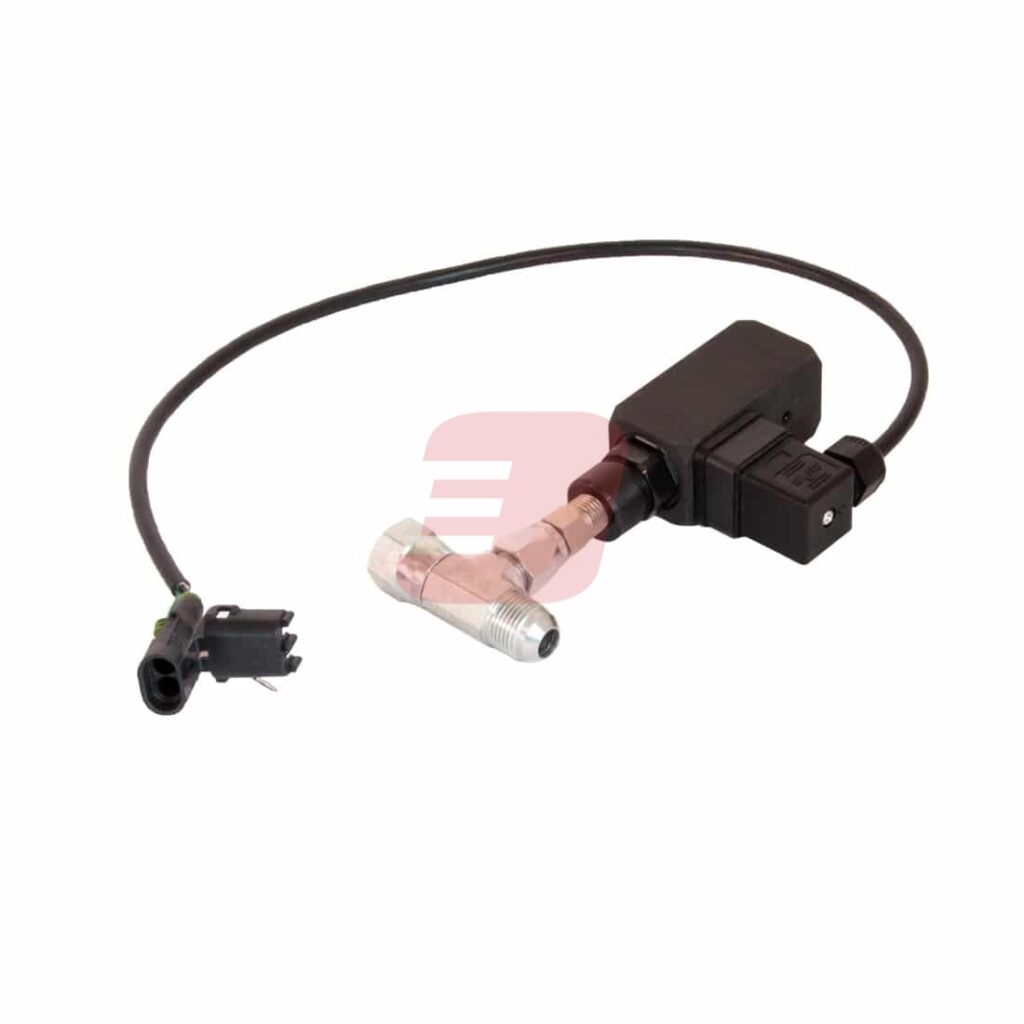
Parts Required (included in AG-K18)
- Hydraulic Work Switch
- Hydraulic “T” Fitting
- Hydraulic Adapter Fitting
- Thread Sealant/Tape
Step-by-Step Instructions
Typical factory mechanical work switches on most seeding implements have an inherent delay when raising or lowering the openers which causes excess seed or fertilizer product to be discharged on the ground before and after each pass in the field, typically at the headlands.
The Red E hydraulic work switch kit, however, engages or disengages the seed delivery system the moment a pressure change is detected in the hydraulic lift circuit thereby greatly increasing the accuracy of your desired start/stop seeding times and minimizing product waste. Installation is simple and typically connected in line next to the hydraulic control block.
- Determine if machine is 2 pin or 3 pin style
Note: Due to the many diverse machine models and configurations available, you may be required to reconfigure or purchase your own applicable electrical connections. It is entirely possible that there are male pins in a male Weatherpack (WP) socket on the OEM harness which would require changing out hydraulic work switch ends (male and male won’t work).
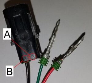
TIP: Temporarily wire switch to drill harness to verify proper function before connecting pins into WP shroud plugs. If backwards, display will indicate machine in up position when it is actually down. If this happens you will need to switch green and red wires on the hydraulic work switch side.The hydraulic switch comes with a 2-pin and 3-pin Weatherpack (WP) shroud (black casing) tied to the end of the electrical cable. There are 3 different wires coming from the hydraulic work switch: red, green, and black. Determine if your machine configuration is a 2 pin or 3 pin style.
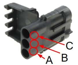
2 PIN STYLE: The black wire/pin should be installed in the B location and is always used. If the switch is “normally open”, fully insert the RED pin into slot A as shown in Figure 2 and 3. The green wire is for systems that have a “normally closed” circuit (do not connect this wire/pin in a “normally open” circuit).
3 PIN STYLE: (Some JD Drills) The black hydraulic work switch wire should be connected to the brown wire, and red to red. The green wire will not be used and should be left unconnected. If possible, plug the unused electrical socket end. If applicable, the electrical casing may then be closed to create a tight seal.
Figure 2: 2 Pin WP Shroud

Figure 3: 3 Pin WP Shroud

- Pre-assemble fittings
Pre-assemble fittings. Note: the adaptor fitting requires Thread Sealant/Tape on the NPT end. Tighten all fittings using the appropriate open-end wrenches.
- Verify supplied hydraulic fittings will work with configuration
Note: Verify supplied hydraulic fittings will fit your configuration. Due to the many diverse machine models and configurations available, you may be required to supply or purchase your own necessary hydraulic fittings.
- Install switch
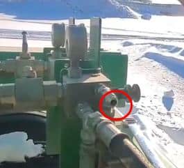
The Switch should be installed in line on the pressure side of the hydraulic lift circuit. For JD drills the most convenient location is on the front of the drill. This is typically located at the back of the down pressure valve block, shown in Figure 4. Simply remove the hydraulic hose, install the hydraulic work switch assembly, & re-attach lift circuit hose. Remember to tighten all connections.
Figure 4: Common Lift Circuit Location

Additional Notes
- The switch can be tied in anywhere within the lift circuit as required.
- On dual rank drills, there can be multiple work switches on the machine. You must select which work switch to tie into and make sure the other switch is disabled. Reference your machine’s owner’s manual.
- Temporarily wire switch and run tractor to verify proper function before final seating of electrical plugs in sockets.
- When possible, leave the factory harness plug intact so that the hydraulic work switch can be quickly unplugged and returned back to the original factory configuration by plugging OEM back into OEM mechanical work switch connector.
- The Hydraulic Work Switch Kit is not recommended for some hoe drills as any leak down of the lift circuit could trip the switch.
Pressure Adjustment
If pressure adjustment is required: Loosen set screw using a 2.5mm Allen wrench. Use 6mm Allen wrench to adjust switching pressure. Adjust switch setting to desired pressure (switch range must not exceed 500-3600 psi). Retighten set screw.
Hydraulic Work Switch Kit
Category: Air Drill Parts
Tags: